Transmitter’s test connection
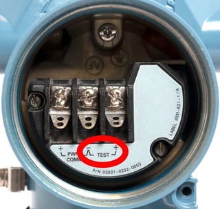
Many process transmitters, specifically pressure transmitters, have a “test connection” in the connection panel. It is typically marked with “TEST” text and it is located next to the normal mA loop connections.
I’m sure you have seen it; in one transmitter, it looks like this:
Purpose of the test connection
The purpose of the test connection is to be able to easily measure the loop current going through the transmitter, without the need to disconnect wires or break the current loop. You just connect your mA meter to the TEST connection and you can see the current that is going through the transmitter, as all the current now goes through your current meter.
When you disconnect your current meter, all the current starts to again go through the internal diode (I will explain diodes soon) in the test connection. At any point, there is no cut in the current loop.
Schematics
As engineers, we just love schematic diagrams, so I need to add some here also.
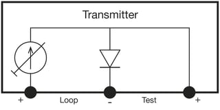
In the transmitter, there is a diode inside the transmitter connected between the test connections. One end of the diode is connected to one of the “loop” connections, and other end of the diode connected to the test connection. Sounds complicated when you read it, but it is very simple. I’m sure a picture will help you to understand this…
With a schematic diagram, it typically looks like this:
What is a diode and does it work?
To better understand this phenomenon, we need to look at what a diode is and how it works.
A diode is a small electronic semiconductor component made with P and N materials. Most electronic devices have many diodes inside, even calibrators… ;-)
An ideal diode will conduct DC current only in one direction. An ideal diode would always conduct current when the voltage over the diode is the right way around. In practice, it is a bit more complicated and the diodes are not ideal.
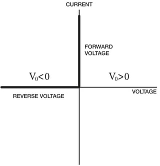
Here’s characteristics of an ideal diode (left) and a realistic diode (right):
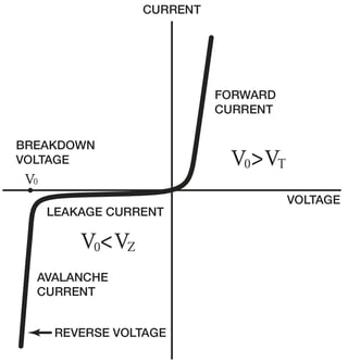
As we can see in the characteristics of a diode (the real one, not the ideal one), the forward current starts flow when the voltage over the diode is large enough and exceeds the threshold voltage. Typically, with a silicon diode the threshold voltage is about 0.6 V. When the voltage is more than this threshold, the diode is “open” and the current goes through it. When the voltage is less than the threshold, the diode is “closed” and no current goes through it.
Current through a transmitter
In normal use of a transmitter, the loop supply effects the diode, so the diode is fully open and all loop current goes through the diode. So actually, the diode doesn’t really do anything, it is not even needed in normal operation and could be replaced with a short-circuit.
But when you connect an mA meter over the diode, all the current starts to go through the mA meter and none of it goes through the diode anymore. Magic!? Well, no magic, just electronics.
Pictures below show how the current goes through test diode (above) or mA meter (below):


Well, this is how it should work, but it does not always work like that in practice. Read on…
How does an mA meter work?
Why am I talking about impedance of a mA meter? What is that impedance?
The way mA meters are normally built, there is an accurate shunt resistor, a few ohms, that the current goes through (R in the picture below). This current causes a voltage drop over the shunt resistor and by measuring this voltage with an A/D converter (V in the picture) we can calculate the current.
The rest is simple mathematics, per the Ohm’s law: I = U/R (Current = Voltage / Resistance).

Unfortunately, some mA meters/calibrators have impedance that is a bit too high, which causes the voltage drop over the resistor to be larger. In most applications, larger impedance is not critical, but with the transmitter’s test connection it is. When the voltage drop becomes larger it causes the test diode to start opening either slightly causing small leakage current, or all the way open.
Why would you put higher impedance in a mA meter? It may be easier to design a mA meter using a bit higher impedance, as then the voltage drop becomes higher and it is easier to measure it internally with A/D converter, since the voltage signal is higher.
For example, if the internal impedance of an mA meter would be as high as 50 ohms, then with a 20 mA current this means that the voltage drop over the mA meter (and test connection’s diode) would be 1 V causing the test diode to be fully open (threshold 0.6 V). This would mean that your mA meter would show hardly any current, although there is a 20mA current going through the transmitter, as all current goes though the test connection.
The above example’s kind of huge error would be easy to notice in practice. But there are also some mA meters with say about 30 ohm internal impedance. This means that with a smaller current the measurement works okay, but when getting closer to 20 mA the voltage drop gets closer to 0.6 V, and the test diode starts to leak and part of the current goes through the diode. This may be difficult to realize, resulting in you trusting the faulty measurement result of your mA meter.
The drawing below shows how the current goes partly through mA meter and partly through test diode, if the mA meter’s impedance is too high:

As the current splits between mA meter and diode, the mA meter is showing only part of the current, so it is displaying a wrong result.


