


How to Calibrate Pressure Gauges: 20 Things to Consider
Pressure gauges are very common instruments in the process industry. As with any measurement device, pressure gauges need to be calibrated at regular intervals to ensure they are accurate. There are many things to consider when calibrating pressure gauges. This article lists 20 things you should consider when calibrating pressure gauges:
What is pressure?
Before we discuss each of the things to consider when calibrating pressure gauges, let’s take a quick look into a few more basic concepts. Pressure is the force that is perpendicular to the surface divided by the area it is affecting. So, pressure equals force per area or p = F / A. There are many different pressure units used around the world, and this can be sometimes very confusing. The engineering unit for pressure, according to the SI system, is Pascal (Pa), being a force of one Newton per one square meter area, 1 Pa = 1 N/m². Because Pascal is a very small unit, it is most often used with coefficients, such as hecto, kilo, and mega.
Pressure types
Several different pressure types exist, including gauge, absolute, vacuum, differential, and barometric. The main difference between these pressure types is the reference point against which the measured pressure is being compared. Pressure gauges are also available for all these pressure types. Also, compound gauges are available, including a combined scale for both positive gauge pressure and vacuum (negative gauge) pressure.
Pressure gauges
When talking about pressure gauges, it is normal to refer to analog pressure indicators that are provided with a pointer needle and a pressure scale. These are normally manufactured according to the EN 837 or ASME B40.100 standards. Often these kinds of analog pressure gauges are built with a Bourdon tube, diaphragm, or capsule. There is a mechanical structure that moves the pointer as pressure increases, causing the pointer to move across the scale. Pressure gauges are divided into different accuracy classes that specify the accuracy of the gauge as well as other attributes. Available pressure ranges are typically divided in steps with coefficients 1, 1.6, 2.5, 4, 6 continuing into the next order of magnitude (10, 16, 25, 40, 60) and so on. The different gauge diameters (of scales) are typically 40, 50, 63, 80, 100, 115, 160, and 250 mm (1½, 2, 2½, 4, 4½, and 6 inches). More accurate gauges typically have a bigger diameter. Pressure connectors are normally parallel pipe threads (G) according to ISO 228-1, or taper pipe threads (NPT) according to ANSI/ASME B1.20.1. There are also digital pressure gauges that have a numeric pressure indication instead of an analog pointer. This article focuses on analog gauges, but most of the principles are valid for both. Pressure gauges are commonly used in all industries and are a very common instrument to calibrate. As with any process measurement device, they should be calibrated at regular intervals to make sure that they are measuring correctly. Gauges are mechanical instruments, which adds to the risk for them to drift due to mechanical stress.
The basic principle of calibration
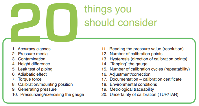
If we simplify the principle of pressure gauge calibration to its minimum, we can say that when we calibrate a pressure gauge, we provide a known accurate pressure input and read the indication on the gauge, and then document and compare them. The difference in the values is the error, and the error should be smaller than the required accuracy for the gauge. This section lists the 20 most common things you should consider when you are calibrating pressure gauges.

Accuracy classes
Pressure gauges are available in many different accuracy classes. Accuracy classes are specified in the ASME B40.100 (accuracy classes from 0.1–5 percent range) and EN 837 (accuracy classes from 0.1–4 percent range) standards. The accuracy class specification most often being “percent of range” means that if the accuracy class is 1 percent and if the scale range is zero to 100 psi, then the accuracy is ±1 psi. Make sure you know the accuracy class of the gauge you are going to calibrate, as this will naturally specify the acceptable accuracy level, but it will also have other effects on the calibration procedure.
Pressure media
When calibrating pressure gauges, the most common pressure media are gas or liquid. Gas is most often regular air, but in some applications, it can be different gases, such as nitrogen. Most commonly, the liquid is water or oil. The pressure media during the calibration depend on the media that is used in the process that the gauge is connected to. Media also depend on the pressure range. Low pressure gauges are practical to calibrate with air/gas, but as the pressure range gets higher it is more practical and also safer to use liquid as the media.
Contamination
While installed in a process the pressure gauge uses a certain type of pressure media; this should be considered when selecting the media for the calibration. You should not use a media during the calibration that could cause problems when the gauge is installed back to the process. Also, the other way around, sometimes the process media could be harmful to your calibration equipment. Dirt inside the gauge can get into the calibration equipment and cause harm. With gasoperated gauges, you can use a dirt/moisture trap, but for a liquid-operated gauge, you should clean the gauge prior to calibration. One of the most extreme process situations is if the gauge is used to measure the pressure of oxygen. If any grease goes into a high-pressure oxygen system during the calibration of the gauge, it can be very dangerous and could cause an explosion.
Height difference
If the calibration equipment and the gauge to be calibrated are at different heights, the hydrostatic pressure of the pressure media in the piping can cause errors. This normally is not an issue when gas is used as the media, as gas is light compared to liquid. But when liquid is used as the media, the liquid in the piping will have a weight due to hydrostatic pressure and can cause errors. The magnitude of the error depends on the density of the liquid and the difference in height, because gravity is pulling the liquid inside the tubing. If it is not possible to have the calibrator and gauge at the same height, then the effect of the height difference should be calculated and taken into account during the calibration.
An example of the effect of hydrostatic pressure:
Hydrostatic pressure is calculated as follows: Ph = p × g × h
Where: Ph is the hydrostatic pressure
p is the density of liquid (kg/m³)
g is the local gravity (m/s²)
h is the height difference (m)
For example, if water is the media (density 997.56 kg/ m³), local gravity is 9.8 m/s², and there is a 1 meter (3.3 feet) difference between the DUT and the reference equipment, this will cause an error of 9.8 kPa (98 mbar or 1.42 psi).
Note that depending on the pressure to be measured, the error caused by the height difference can be significant.
Leak test of piping
If there are any leaks in the piping during the calibration, unpredictable errors can occur. Therefore, a leak test should be done before calibration. The simplest leak test is to pressurize the system, let the pressure stabilize for some time, and monitor that the pressure does not drop too much. Some calibration systems (pressure controllers) may be able to maintain the pressure even in case of a leak, if there is a continuous controller adjusting the pressure. In that case, it is difficult to see a leak, so the controller should be closed to enable a closed system for a leak test. Adiabatic effect should also always be considered in closed systems, especially with gas media, as explained in the next item.
Adiabatic effect
In a closed system with gas as the pressure media, the temperature of the gas effects the volume of the gas, which has an effect on the pressure.
When pressure is increased quickly, the temperature of the gas will rise, and this higher temperature makes the gas expand, so it has a bigger volume and higher pressure. When the temperature starts to cool down, the volume of the gas becomes smaller, and this will cause the pressure to drop. This pressure drop may seem like a leak in the system, but it is actually caused by the adiabatic effect due to the change in the gas temperature. The faster the pressure is changed, the bigger the effect is. The pressure change caused by this effect will gradually get smaller as the temperature stabilizes. So, if you change the pressure quickly, make sure you let it stabilize before judging whether or not there is a leak in the system.
Torque force
Especially for torque-sensitive gauges, do not use excessive force when connecting pressure connectors to the gauge, as it may damage the gauge. Follow the manufacturer’s instructions for the allowed torque force. Take the time to use proper tools and appropriate adapters and seals.
Calibration/mounting position
Because pressure gauges are mechanical instruments, their position will affect the reading. Therefore, calibrating the gauge in the same position as it is used in the process is recommended. The manufacturer’s specifications for the operation/mounting position should also be taken into account.
A typical specification for a mounting position is that a change of 5 degrees in position should not change the gauge indication by more than half (0.5 times) of the accuracy class.
Generating pressure
To calibrate a pressure gauge, you need to source the pressure applied to the gauge. There are different ways to do that: you can use a pressure hand pump, a pressure regulator with a bottle, or even a dead weight tester. A dead weight tester will provide a very accurate pressure, and you do not need a separate calibrator to measure the pressure, but a dead weight tester is expensive, not very mobile, requires a lot of attention to use, and is sensitive to dirt. It is more common to use a pressure calibration hand pump to generate pressure and an accurate pressure measurement device (calibrator) to measure the pressure. A pressure controller can also be used to supply the pressure.
Pressurizing/exercising the gauge
Due to its mechanical structure, a pressure gauge will always have some friction in its movement, and may change its behavior over time; therefore you should exercise it before calibration. This is especially the case if the gauge has not been applied with pressure for a while. To exercise, supply the nominal max pressure and let it stay for a minute, then vent the pressure and wait a minute. You should repeat this process two or three times before starting the actual calibration cycle.
Reading the pressure value (resolution)
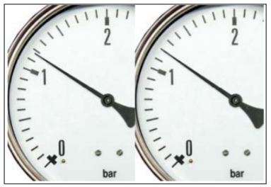
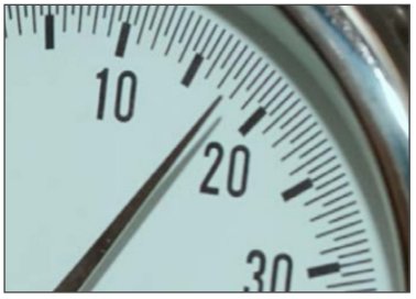
The scale in pressure gauges has limited readability. It has major and minor scale marks, but it is difficult to accurately read the pressure value when the indicator is in between the scale marks. It is much easier to see when the needle is exactly at a scale mark. Therefore, the recommendation is to adjust the input pressure so that the needle is exactly at an indication mark, and then record the corresponding input pressure. If you just supply a certain accurate input pressure and then try to read the indicator, it will cause errors due to limited reading accuracy. Also, it is important to look at the indication perpendicular to the gauge scale. Many accurate gauges have a reflecting mirror along the scale, behind the needle pointer. This mirror helps you read it, and you should read it so that the mirror reflection of the needle is exactly behind the actual needle. Then you know that you are looking perpendicularly/straight at the gauge. If the gauge has a digital indicator, then the resolution (reading accuracy) is totally different. You can read the digital indicator equally accurately at any point of its range.
Number of calibration points
The different accuracy classes of gauges will determine the different number of calibration points. For the most accurate gauges (better than 0.05 percent), you should use the “comprehensive calibration procedure.” The calibration should be performed 11 calibration points across the range (zero point plus 10 percent steps) with three cycles in rising and falling pressure. For the mediumaccuracy class gauges (0.05–0.5 percent), use a “standard calibration procedure” with 11 points, but fewer repeated cycles. The less accurate gauges (class equal or greater than 0.5 percent) are to be calibrated with the “basic calibration procedure” with six calibration points (zero point plus 20 percent steps) with rising and falling pressure. In practice, gauges are sometimes calibrated with fewer calibration points. Hysteresis is discussed later, but to find the hysteresis, the calibration should be done with increasing and decreasing pressure points. Naturally, the number of calibration points and cycles also depends on the application, criticality, and accuracy requirement.
Hysteresis (direction of calibration points)
Again, due to its mechanical structure, a pressure gauge may have some hysteresis. This means that the indication is not exactly the same when a pressure point is approached with an increasing pressure compared to a decreasing pressure. To find the amount of hysteresis, you should calibrate the gauge with increasing and decreasing calibration points, i.e., to first go up and then go down with pressure. While doing this, it is important to make sure that the pressure moves only in the desired direction. For example, when you calibrate with increasing pressure you must make sure that you do not decrease the pressure at any point when fine adjusting the pressure, as this will cause you to lose the hysteresis information. If you overshoot the target point with increasing pressure, you need to come way back down and then increase the pressure again to the target point.
“Tapping” the gauge
Sometimes a mechanical pressure gauge may need a gentle tapping in order to make sure that it is released from any friction or lost flexibility, especially if it has not been exercised in normal use. During the calibration, once the input pressure is stabilized, you can gently tap the gauge to see if the indication changes. Of course, you need to tap gently so you do not damage the gauge.
Number of calibration cycles (repeatability)
During calibration, the calibration cycles are repeated several times to determine the repeatability of the gauge under calibration. If the gauge to be calibrated has bad repeatability, it will give different results during different calibration cycles. If you only calibrate it with one cycle, you will miss the repeatability information and part of the truth. As mentioned earlier, the most accurate gauges should be calibrated with three calibration cycles. In practice the repeatability is often tested as a type test for certain instrument types (make/model), and once the typical repeatability is known, the actual calibration is carried out in practice with just a one-calibration cycle, taking the typical repeatability into consideration.
Adjustment/correction
If the As Found calibration shows that the gauge is not within the accuracy requirements, something needs to be done. In most cases the gauge should be adjusted so that it will be within the allowed tolerance levels. After adjustment, the gauge needs to be calibrated again (As Left) to verify the condition it was left in. If it is not possible to adjust the gauge in question, then a correction coefficient can be calculated, and this coefficient must be taken into account in normal usage. This will, of course, make the usage more difficult. If the gauge has a big error, then it is best to repair/replace it and not try to adjust it, as most likely it will not stay stable in the future.
Documentation – Calibration certificate
One crucial aspect for calibration is, of course, to document calibration results in a calibration certificate. The certificate should document the applied pressure and the indication of the gauge as well as an error calculation (difference of applied pressure and indication). Certainly, the certificate needs to contain other information also, as stipulated by standards/regulations, including calibration uncertainty. If you make the certificate manually, it means that you write the gauge’s indication and the applied pressure on paper and then calculate the error manually. You can also use automated calibration equipment that will perform the documentation and calculations automatically and transfer the results to the computer for calibration software to store/print the results.
Environmental conditions
Most gauges specify temperature effect, and this should be taken into account. Most often you calibrate the gauge in the normal room temperature, but the gauge may be used at a different temperature in the process. This difference in temperatures may cause differences in gauge accuracy between calibration and process usage. Environmental conditions (temperature and humidity) during the calibration should be recorded in the calibration certificate.
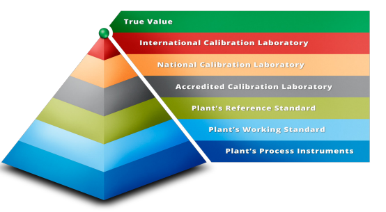
Metrological traceability
As with any calibration, you must ensure that the reference standard you are using to measure the applied pressure to the pressure gauge has a valid calibration certificate and that its calibration is traceable to the appropriate national standards (metrological traceability).
Uncertainty of calibration (TUR/TAR)
With any calibration, you should be aware of the total uncertainty of the calibration measurements, otherwise the result will not have much value. Awareness of calibration uncertainty seems to be rising, and it is also included more frequently in relevant standards and regulations. In some areas the test uncertainty ratio (TUR) or test accuracy ratio (TAR) is used instead of the uncertainty calculation. The concept of this is to make sure that you have a calibrator (or reference standard) that is several times more accurate than the instrument to be calibrated, and if you know this, you do not need to calculate uncertainty. One of the most commonly used ratios is 1:4, meaning that the calibrator’s specs are four times better than the specs of the gauge to be calibrated. It is good to notice, anyhow, that when using this TUR/TAR ratio method, you are not aware of all the relevant uncertainty components of your calibration process and you do not know how good the calibration really is. Therefore, calculating the total uncertainty of the calibration is the more recommended method.


